
Searching for a universal “standard size” is the wrong starting point for a commercial box gutter. A warehouse owner can't safely choose a width from a catalogue, connect it to an old downpipe and assume the system will cope with the next intense storm. Australian box gutter sizes are engineered from hydraulic demand, not selected by appearance or nominal sheet-metal dimensions.
That distinction matters because concealed gutters fail without warning. Water can surcharge against roof junctions, parapets and wall penetrations before anyone sees a stain inside the tenancy. A compliant design must account for catchment area, local rainfall intensity, gutter geometry, fall, outlet capacity, freeboard and an independent overflow route.
Table of Contents
- The Myth of Standard Box Gutter Dimensions
- Hydraulic Sizing Principles and Australian Standards
- Freeboard and Independent Overflow Provisions
- Common Commercial Profiles and Configuration Limits
- Downpipe Pairings and Maintenance Access
- Worked Example for an Industrial Warehouse Roof
- Installation Best Practices and Compliance Verification
The Myth of Standard Box Gutter Dimensions
The popular advice is simple: make the box gutter wider if the roof is large. That approach may sound practical, but it leaves out the parts of the drainage system that usually create the failure. A wider sole won't compensate for a restricted rainhead, undersized downpipe, inadequate fall or an overflow that discharges into the roof cavity.
Commercial and industrial box gutters are custom-engineered profiles. The National Construction Code directs box gutters to be designed in accordance with AS/NZS 3500.3, or addressed through a documented Performance Solution, rather than chosen from generic eaves-gutter tables. The Victorian Building Authority likewise directs designers to calculate hydraulic capacity and overflow provisions instead of relying on a nominal width or depth. The VBA box-gutter technical guidance sets out the design approach used for the relevant Australian details.
Why nominal dimensions mislead
Two gutters with the same sole width can perform differently if their depth, longitudinal grade, outlet arrangement or rainhead geometry differs. A long run carrying water to a single end outlet faces a different hydraulic problem from a shorter run with a sump and multiple discharge points. The roof planes feeding the gutter also matter. A valley or large uninterrupted roof plane can concentrate inflow at one location.
Generic tables can still help a contractor discuss the physical constraints of a product. They can't replace the calculation that proves the proposed profile will convey the site's design flow without unacceptable surcharge. They're particularly unsuitable for low-slope commercial roofs, where a concealed overflow can send water into insulation, ceilings, electrical areas or occupied premises.
Practical rule: Treat a quoted box-gutter width as a starting geometry, not as evidence of compliance.
Owners comparing broader roof drainage options can review top gutter solutions for context, but a Sydney warehouse or strata building still needs a site-specific hydraulic specification. The right question isn't “What size box gutter do I buy?” It's “What inflow must this system carry, and where does excess water go if the primary outlet is restricted?”
That change in question prevents a common procurement mistake. The cheapest quote often lists a gutter profile but says nothing about the rainfall basis, sump capacity, freeboard or emergency discharge path. Those omissions can become expensive once the roof is sheeted over and access to the concealed drainage is limited.
Hydraulic Sizing Principles and Australian Standards
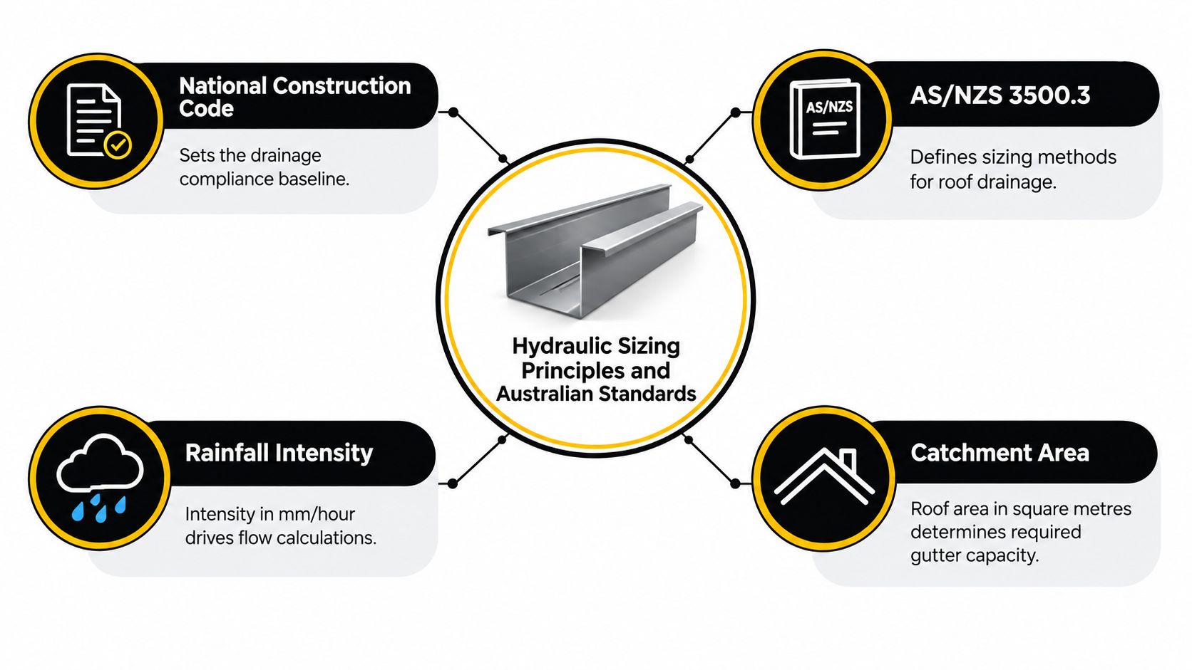
A compliant box-gutter design starts with the peak inflow from each contributing roof plane. The designer establishes the catchment area, applies the local design rainfall intensity and determines how much water reaches each gutter section and outlet. Gutter width and depth then follow from the required hydraulic capacity, rather than dictating it.
The NCC directs box gutters to AS/NZS 3500.3 or to a documented Performance Solution. The standard provides the design procedure and hydraulic-capacity verification framework, while the NCC establishes the compliance baseline for roof drainage. The NCC gutter provisions are useful when checking whether a proposed commercial detail has been treated as an engineered drainage system rather than an ordinary eaves gutter.
The variables that control capacity
The calculation needs more than roof area. A sound design considers:
- Catchment area: Each roof plane must be traced to the gutter section or outlet it feeds. Water from separate planes may combine at a valley, sump or rainhead.
- Rainfall intensity: Short-duration intense rainfall can govern the design, especially on Sydney and NSW projects. The relevant value is site-specific, not a generic national assumption.
- Gutter grade: Consistent longitudinal fall affects how quickly water reaches the outlet. Low spots can hold water and reduce effective capacity even where the nominal cross-section appears adequate.
- Outlet and downpipe capacity: The gutter can only discharge as quickly as its outlet and downstream pipework allow. A narrow outlet becomes the bottleneck.
- Hydraulic losses: Sumps, transitions, bends, outlet geometry and changes in depth affect flow behaviour.
- Overflow provisions: The system must manage exceedance conditions independently from the primary drainage path.
The design basis is a 1% annual exceedance probability, historically described as a 1-in-100-year average recurrence interval. That means the nominated design rainfall has a 1% probability of being exceeded in any given year, as explained in the Victorian guidance linked above. It doesn't mean a severe event occurs only once in a century, and it doesn't justify ignoring maintenance or blockage.
For a local illustration, NCC material gives Albury in NSW a five-minute rainfall intensity of 139 mm/h for the relevant design context, with overflow measures required to cope with a 1% AEP event. That example demonstrates why a designer must use location-specific rainfall data. The number is not a Sydney design value, and it shouldn't be copied into a Sydney specification.
A property owner who wants a general explanation of how gutter geometry is discussed in other building contexts can also review HIBCO ROOF LLC sizing tips. For Australian commercial work, however, the NCC and AS/NZS 3500.3 framework remains the controlling reference, with the design documented for the actual roof.
For related Australian drainage considerations, see the commercial gutter and drainage guide. The useful deliverable isn't a single dimension. It's a coordinated profile showing how the roof catchment, rainfall basis, gutter, sump, rainhead, downpipe and overflow route work together.
Freeboard and Independent Overflow Provisions
Normal flow capacity is only half the safety calculation. A box gutter also needs to protect the building when the primary outlet is blocked, restricted or overwhelmed. Leaves, sediment, bird nests and roof debris can reduce the effective opening, while a downstream stormwater restriction can prevent a correctly sized outlet from discharging freely.
Australian guidance includes 30 mm of freeboard in the box gutter. That vertical allowance helps reduce the risk of wind-driven water spilling into the building before the overflow system operates. It isn't spare capacity that allows a contractor to undersize the gutter. It's a protective margin within a properly calculated arrangement.
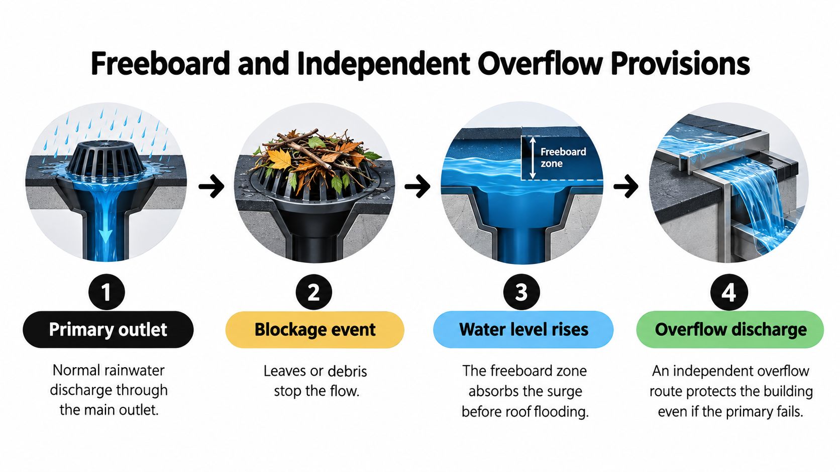
What should happen during a blockage
A strong system follows a clear sequence:
- Normal rainfall reaches the primary outlet. The gutter conveys design flow to the sump, rainhead and downpipe arrangement.
- The primary path becomes restricted. Debris or downstream surcharge reduces discharge, so the water level starts to rise.
- Freeboard provides separation from vulnerable junctions. The rising water must reach the overflow mechanism before it spills into the roof or wall construction.
- The independent overflow discharges to atmosphere. Water leaves through a visible or safely directed route rather than depending on the blocked primary downpipe.
The overflow must be independent. It can't just connect to the same restricted pipe and still be treated as a reliable emergency path. Victorian plumbing guidance requires the overflow to discharge to the atmosphere, and the rainhead arrangement must be designed for surcharge conditions. This is particularly important where the gutter is concealed, because an internal overflow can remain unnoticed until insulation, plasterboard or electrical components are damaged.
Rainhead and weir details
The relevant Victorian guidance identifies a 25 mm lower position for the rainhead overflow weir relative to the box-gutter sole in the referenced configuration. It also includes standard overflow-channel widths of 200 mm, 300 mm and 450 mm. These are configuration limits within the deemed-to-satisfy detail, not universal dimensions for every roof.
The overflow discharge path deserves the same attention as the opening itself. Direct water to a location where occupants can identify a problem and where the façade, pavement, electrical equipment and neighbouring property won't be damaged. An overflow that empties behind cladding or into a ceiling cavity has failed as a practical safeguard, even if a slot exists in the sheet metal.
A box gutter must not depend on perfect maintenance. Design the emergency path so one blocked primary outlet doesn't turn a drainage fault into internal flooding.
Strata managers should ask to see the overflow location in drawings and during inspection. Warehouse owners should check whether a new gutter connects to a legacy rainhead or downpipe that was never designed for the current catchment. Increasing the gutter width alone won't fix a system where the rainhead or downstream connection remains the bottleneck.
Common Commercial Profiles and Configuration Limits
Physical dimensions matter, but they only make sense when read as part of a tested configuration. Australian guidance identifies practical design-flow values from approximately 3 to 16 litres per second for the referenced box-gutter arrangements. It also shows that a 200 mm sole width cannot accommodate flow rates above 10.5 litres per second in the relevant configuration. These figures demonstrate why a wider-looking gutter isn't automatically a higher-capacity solution. The VBA common enquiries and faults guidance explains the configuration limits and associated rainhead details.
Configuration limits and what they mean
| Configuration element | Standard dimension or limit | Design implication |
|---|---|---|
| Referenced practical design-flow range | Approximately 3 to 16 L/s | The proposed profile, sump, outlet and overflow arrangement must suit the calculated flow. |
| 200 mm sole width | No more than 10.5 L/s in the referenced configuration | Higher flow requires the arrangement to be revised, not simply accepted because the sole appears wide. |
| Overflow-channel widths | 200 mm, 300 mm or 450 mm | Select the applicable configuration and verify it against the hydraulic and surcharge conditions. |
| Rainhead overflow weir | 25 mm below the box-gutter sole | Provides the specified relationship for emergency discharge in the relevant detail. |
| Upstream sole dimension | 40 mm | Applies to the relevant referenced detail and isn't a universal substitute for design. |
| Downstream sole dimension | 60 mm | Must be read with the complete rainhead and outlet configuration. |
Width versus complete system capacity
A contractor may propose widening the sole because it's easy to describe and easy to fabricate. That can work where the hydraulic calculation shows the revised section has sufficient capacity, but it won't solve every failure mode. A larger sole still needs suitable depth, grade, sump geometry and freeboard. The rainhead overflow must also operate before water reaches vulnerable roof junctions.
The practical trade-off is between a compact profile and a more generous engineered arrangement. A compact gutter can suit a constrained architectural detail, but it leaves less tolerance for installation error, debris and uneven falls. A larger profile may require more structural coordination, deeper fascia work or a revised cladding junction. Neither option is automatically right.
If the flow exceeds the capacity of the referenced sole arrangement, revise the gutter, sump, rainhead and overflow together.
For a warehouse owner, this table is a useful review tool, not a shopping list. Ask the designer to identify which configuration has been used, the flow it is expected to carry and how the overflow behaves under surcharge. A quote that lists only “box gutter, 200 mm” hasn't answered those questions.
Downpipe Pairings and Maintenance Access
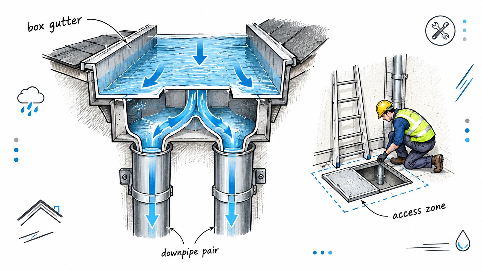
A box gutter is only as effective as the drainage chain below it. Water must move from roof plane to gutter, through the sump or outlet, into the rainhead and downpipe, then into the lawful stormwater connection. If any part has less capacity than the section above it, that point controls the system.
This is why connecting a new engineered gutter to legacy downpipes can create a concealed bottleneck. The new gutter may accept the roof inflow, but the old outlet or downstream connection can surcharge and force water back into the rainhead. The specification should identify the capacity and condition of each downstream component, not just the visible gutter channel.
Make maintenance part of the design
Internal box gutters collect debris in places that are difficult to see from the ground. Access should allow a trained person to inspect the gutter, clear the outlet and confirm that the overflow opening is unobstructed without damaging the roof membrane or weatherproofing.
Useful provisions can include:
- Safe inspection access: Provide a practical route to the gutter, with roof access coordinated with workplace safety requirements.
- Outlet visibility: Make strainers, sumps and rainheads accessible for cleaning and inspection.
- Debris control: Use guards only where they don't reduce the effective opening or make cleaning more difficult.
- Downstream inspection points: Keep access to relevant stormwater junctions so a blockage isn't mistaken for a gutter-capacity problem.
- Condition records: Photograph concealed areas before closing the roof and retain the hydraulic design with maintenance documentation.
The maintenance plan should reflect the site. A warehouse beneath trees, a retail complex with rooftop plant and a clean industrial roof won't collect debris in the same way. The responsible manager needs to know who checks the primary outlet, who checks the overflow and what signs require immediate attendance.
More practical guidance is available in this commercial gutter maintenance resource. The important point is that access isn't an optional convenience added after installation. It determines whether the system can continue to perform as designed.
Worked Example for an Industrial Warehouse Roof
Consider a proposed industrial warehouse in NSW with several roof planes draining towards an internal box gutter. The project team initially presents a generic rectangular profile and assumes the existing downpipe locations can remain. That proposal is incomplete because it doesn't identify the design rainfall basis, the flow from each plane or the restriction created by the existing outlets.
The hydraulic designer first maps the roof catchments. Each contributing plane is assigned to the relevant gutter section, with concentrated inflows identified at valleys and changes in direction. The designer then applies the local rainfall intensity required for the project and calculates the peak inflow reaching each sump. The result is a flow requirement for each part of the gutter, not one undifferentiated number for the entire roof.
How the design changes
The first profile may appear adequate under ordinary rainfall, but the calculation shows that the outlet arrangement creates a bottleneck during the nominated design event. The team has several possible responses:
- Revise outlet locations: Relocating or adding discharge points may reduce the flow carried by a particular gutter run.
- Increase hydraulic depth or width: A revised cross-section can provide additional capacity where the roof geometry permits it.
- Enlarge the sump and rainhead: A bigger gutter alone won't help if water enters a restricted collection point.
- Upgrade downstream pipework: The downpipe and stormwater connection must accept the discharge without backing up.
- Rework the overflow: The independent weir or channel must discharge safely before water reaches the building envelope.
The design team then checks the proposed longitudinal grade and depth development towards each outlet. They verify that the freeboard remains available and that the overflow will cope if the primary route is restricted. The final drawing should show the gutter profile, sump dimensions, rainhead arrangement, outlet capacity and emergency discharge path.
A change in catchment area or local rainfall intensity can materially alter the result. That doesn't mean the contractor should add an arbitrary safety margin or guess a larger sheet-metal section. It means the calculation must be updated, then the entire drainage chain reviewed.
The finished design is a coordinated profile, not a product label.
For the warehouse owner, the review question is straightforward: can the project team show how water from every contributing roof plane reaches a primary outlet and how excess water leaves safely if that outlet is restricted? If the answer is only a nominal width, the design hasn't been demonstrated.
Installation Best Practices and Compliance Verification
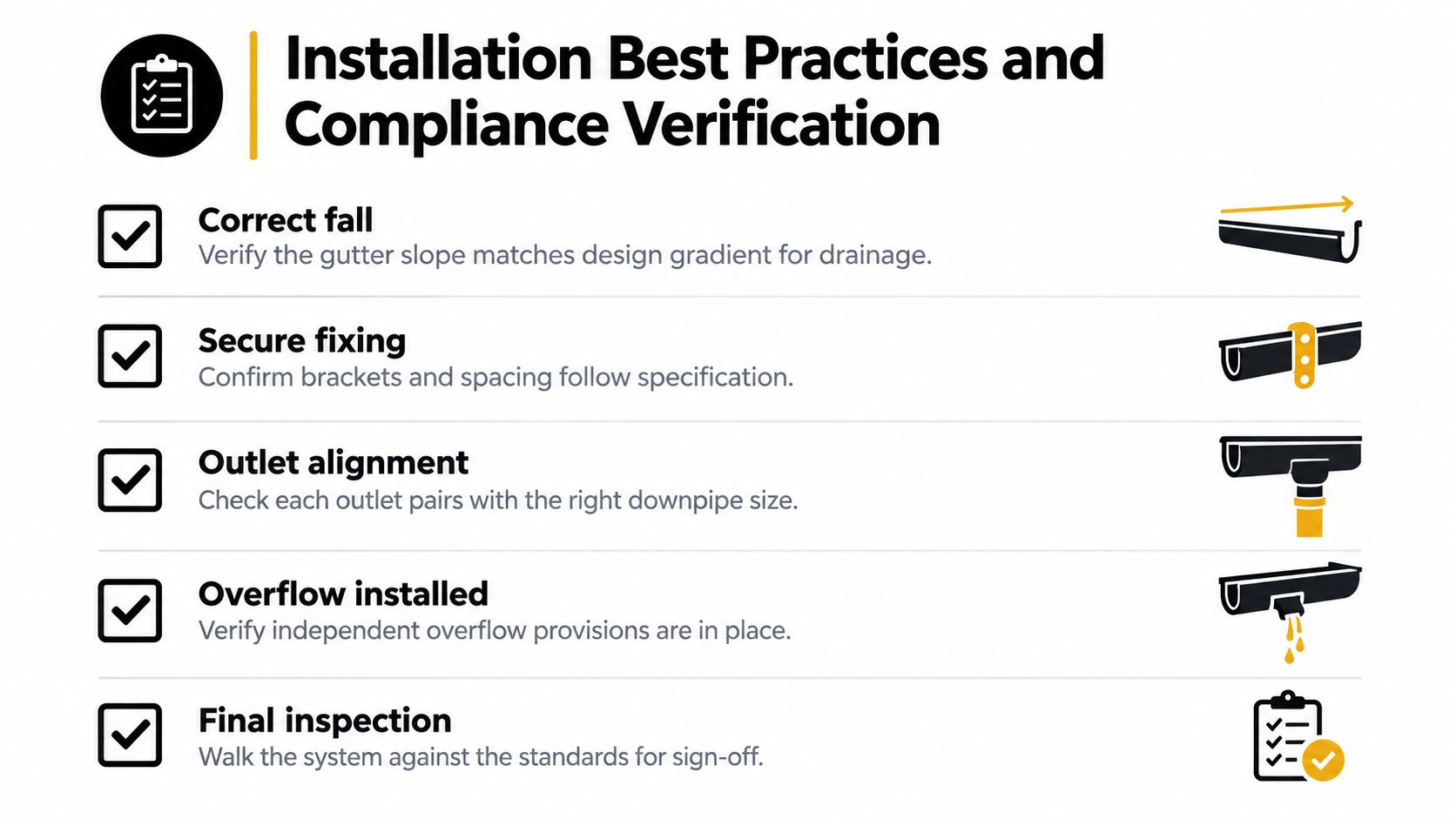
Hydraulic calculations only protect the building when the installer reproduces the intended geometry. A gutter with inconsistent fall, poorly aligned outlets or an obstructed overflow won't perform like the drawing.
Before sign-off, request documentation that identifies:
- Rainfall basis: Confirm the local design rainfall and the applicable 1% AEP event.
- Catchment mapping: Check that each contributing roof plane has been included.
- Primary capacity: Verify the gutter, sump, rainhead and downpipe arrangement as one system.
- Freeboard: Confirm the specified freeboard remains available after installation.
- Overflow route: Trace the independent discharge path to atmosphere and confirm it won't damage the building.
- Installation geometry: Inspect consistent grade, correct depth development and aligned outlets.
- Maintenance access: Confirm that future inspection and cleaning can be carried out safely.
Internal junctions and penetrations need careful sealing, but sealant isn't a substitute for correct falls or hydraulic capacity. The contractor should also check that the gutter hasn't been distorted during fixing and that no liner, mesh or debris has reduced the effective outlet area.
The box-gutter installation guidance can help property teams prepare questions for a contractor, but the project documents should remain specific to the building. Don't accept a generic quote as proof that the drainage complies with the NCC or AS/NZS 3500.3.
Commercial Roofers offers box-gutter installation, repairs, replacement, inspections and associated commercial roof drainage work for strata properties, warehouses and industrial sites across Sydney and NSW. Their team can review catchment, outlet, overflow and maintenance-access requirements, then provide a documented approach for the existing roof or planned project. Visit Commercial Roofers to discuss a site-specific box-gutter assessment.